
Cat Antennas
2025-08-10
This material was first featured in the 'Cat Antennas' section of my research antenna collection GitHub repository.
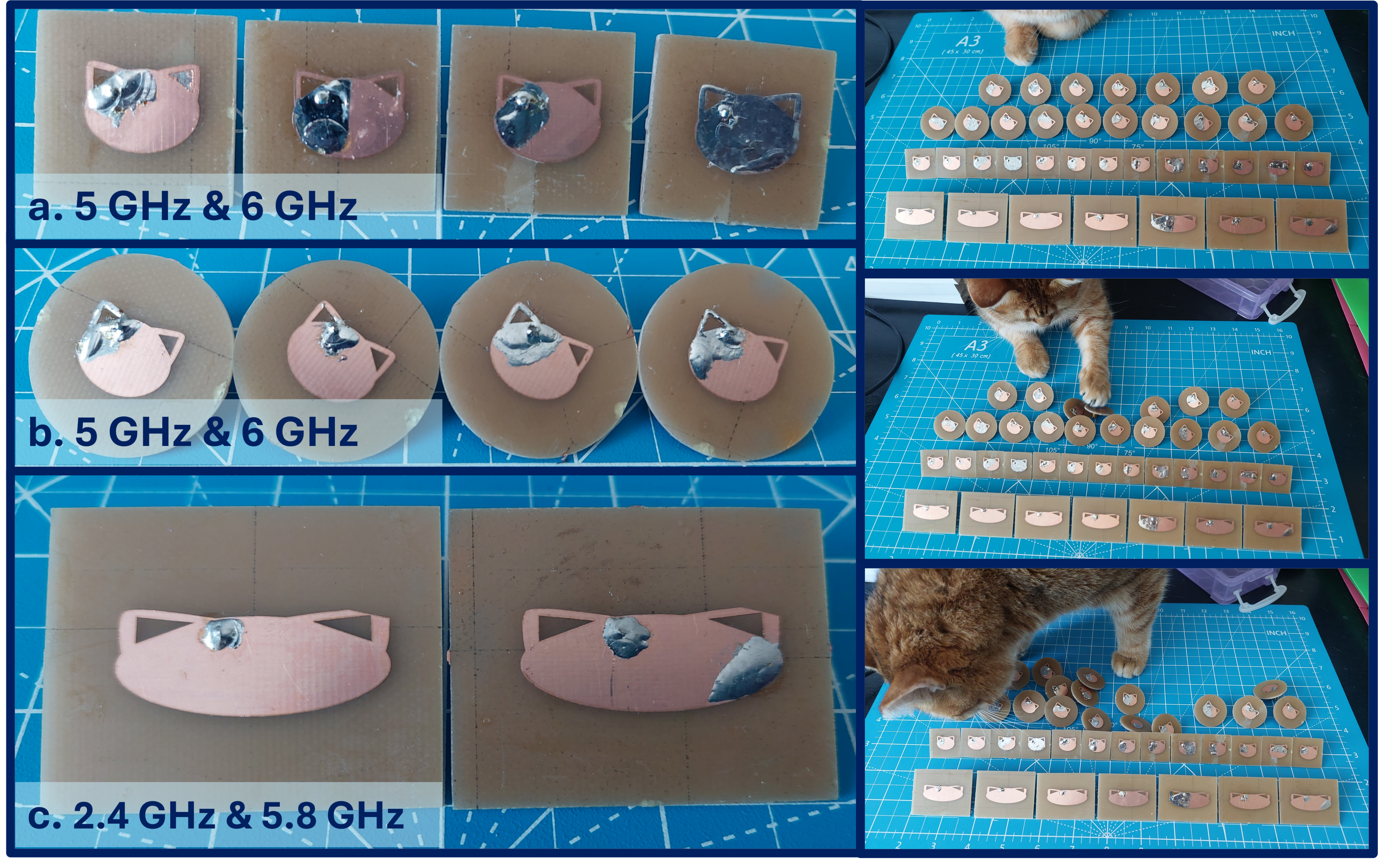
The Cat Antenna Collection is a group of design where the conductor on the planar patch looks like the outline of a cat's face, complete with ears. These antennas are modified oval patches on double-sided copper FR4 with permittivity of ~4.4. They are designed to operate at two independent and tunable frequencies.
The design features a probe-fed configuration with a full copper ground plane and a decorative conductor. The conductor is a modified oval patch design where triangular 'ears' have been added to resemble a cat. This design has been simulated and then verified experimentally with multiple frequency pairs, but targeted Wi-Fi frequencies (i.e., 2.4 GHz, 5 GHz, 5.8 GHz, 6 GHz) were the preferred test designs so that we could use them for wireless transmission demos. Each antenna has two frequencies that can be tuned independently via different dimensional aspects - one frequency is controlled by the cheek-to-cheek distance, while the second frequency is determined by the head-to-chin distance. Simulation results show little preference for which orientation produces the lower frequency.
The design demonstrates good tolerance to manufacturing variations; even to the point where decorative 'calico spots' created with solder during assembly do not impact performance in a noticeable or replicable way. The design is sensitive to the probe location, which is placed towards the left ear. In both simulation and experiments, any deviation from this location (on the front) causes changes in the return loss (S11) balance. To prevent an electrical short, a 1/4 in drill bit was used to remove a circle of copper from the ground plane around the probe location. A drill was used to ensure a consistent size of removal, and we were careful to not drill beyond the surface copper and into the FR4. This antenna design was NOT sensitive to this copper removal process placement, as long as it was close to being centered on the probe feed location. The size of the drill bit was chosen so that the removed copper radius was roughly that of the Teflon on the SMA connector used for the probe feed. The dual frequencies achieve better balance (i.e., that the dual band frequencies are roughly the same with regards to S11 and gain) when implemented on a round ground plane rather than rectangular, which was not completely unexpected as the rectangular design would have several places where the conductor is close enough to the edge of the board for there to be potential issues with the 'edge effect'. Both hand-cut and milled board outlines produced similar measured results, so this is an issue with the shape of the ground plane.
AntennaCAT was used to test Particle Swarm Optimization (PSO) variations on the cat antennas described here. The oval-based antennas, unlike the AntennaCAT logo antennas, are tunable by hand and mathematically describable without simulation. PSO has been used on many, if not all, of the designs in the Research Antenna Collection for either experimental purposes or out of curiosity for performance. PSO was able to place the probe for a balanced S11 and Gain between the two frequencies of the oval design, but the difference in the placement was only significant in simulation. That is, the placement found by PSO was optimal by nanometers, and any deviation from that exact placement (which was too specific for hand assembly) preformed the same as the original placement. It turns out that probe location is extremely sensitive, and the changes due to being slightly out of place with the feed are not significant.
A build of materials, measurement results, and .DXF files for some of the cat antennas are available at https://github.com/LC-Linkous/research_antenna_collection
#antennacat, #antennas, #examples